The chucks of the DBF-series are not suitable for applications with high requirements on clamping force.
Therefore the chucks are not suitable for turning or milling (exceptions might be micro turning or milling). Our chucks are specifically designed for low clamping forces but highest demands on accuracy.
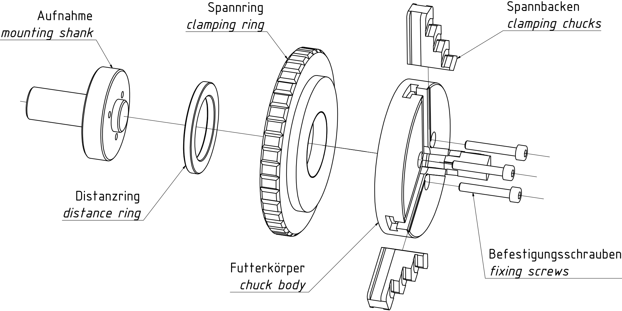 The fixing screws are mounted from the front side of the chuck.
Note that there is no distance ring for some chucks (DBF34, DBF55, DBF63) or the distance ring is screwed on the chuck body (DBF140x58).
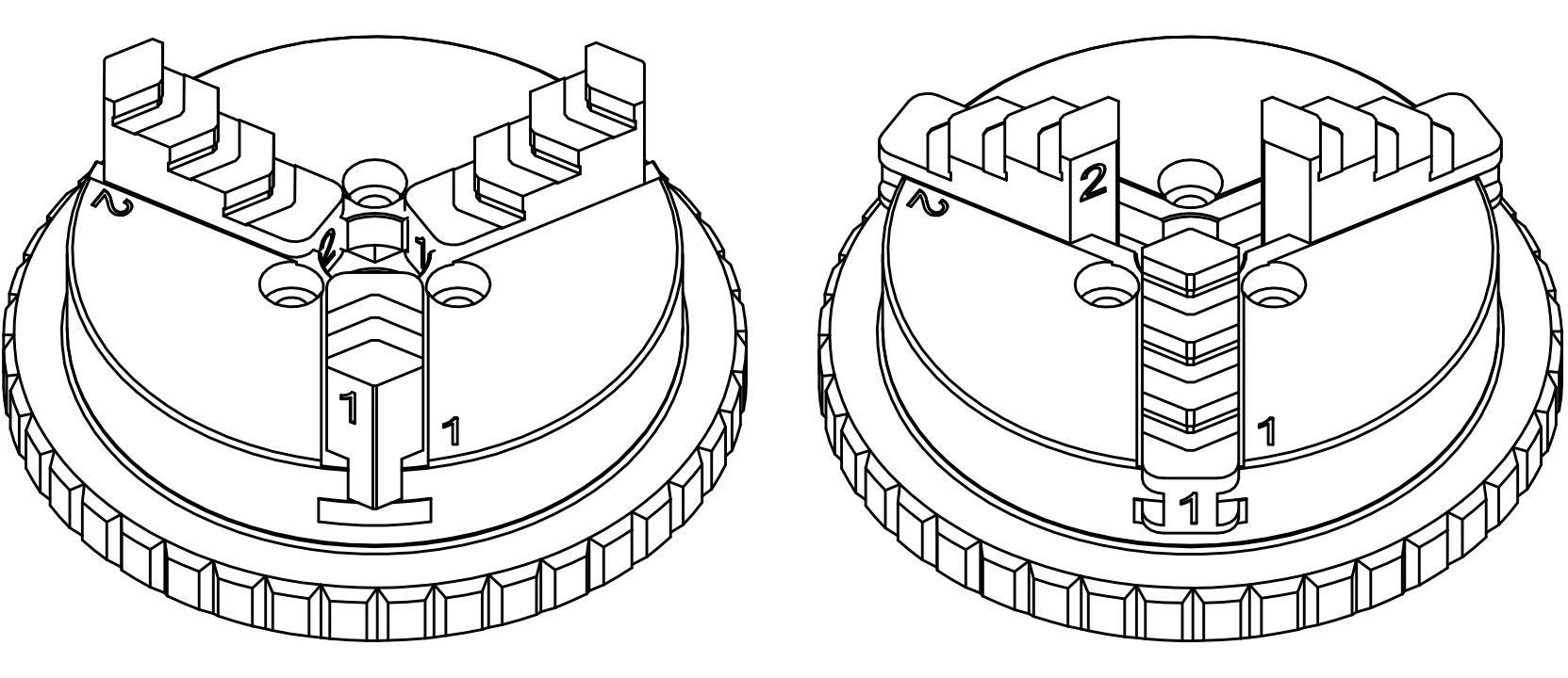
Yes, they are. But in order to reverse them, you need to put them in a different position in the chuck. Note that each jaw has two numbers marked on.
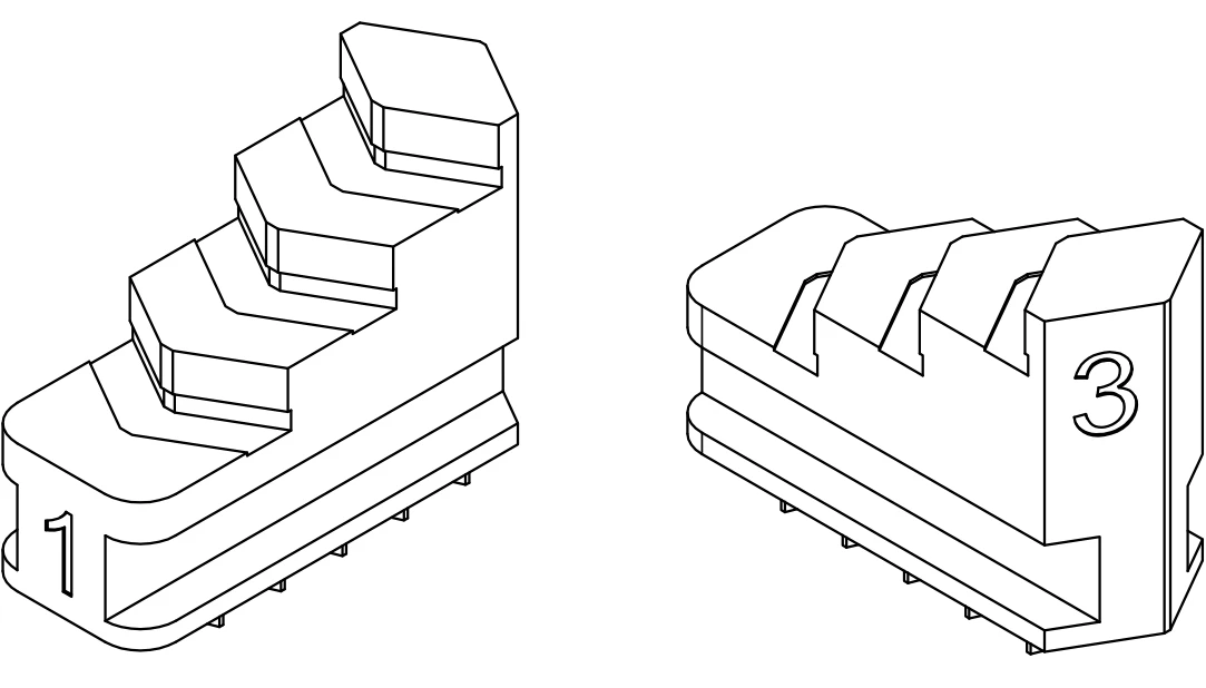
The number which points to outside must match with the number on the chuck body.
The standard jaws are made of made of a hardened stainless steel, which is magnetic.
But non magnetic jaws made of bronze are available. The material of chuck body and the clamping ring is depended on the chuck type.
Please contact for further information.
Wir empfehlen nachfolgenden Drehmomente beim Anziehen der Schrauben:
| Typ | Schrauben | Drehmoment |
|---|---|---|
| DBF34 | M2 | 0,3 Nm |
| DBF55 | M3 | 0,8 Nm |
| DBF63 | M3 | 0,8 Nm |
| DBF140x58 | M3 | 0,8 Nm |
| DBF100 | M4 | 1,9 Nm |
| DBF160 | M6 | 6,3 Nm |
Yes, but note that the jaws are hardened to HRC54+2.
Yes, but we need the corresponding chuck for this. Each jaw must be ground in the chuck it will be used in, in order to get a good radial runout.
To ensure the chucking characteristics, a suitable lubricant must be used. We recommend:
For standard and underwater applications:
- AGIP GR Mu EP 2 (grease based on lithium soap base with additives)
For usage in vacuum:
- Fluoronox MS30/2 (grease based on Perfluoropolyether und PTFE)
Option 1 – alignment by hand
The most simple way of mounting the chucks is by using an even surface with threaded holes on the correct bolt circle. The chucks then needs to be aligned. Therefore a testing pin needs to be clamped. Then the radial run-out must be corrected carefully using a lever arm test indicator.
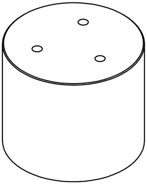
| Type | Ø of contact surface | Thread | Screw hole circle |
|---|---|---|---|
| DBF34 | Ø32 | 3×M2 | Ø16,5 |
| DBF55 | Ø34 | 3×M3 | Ø18 |
| DBF63 | Ø34 | 3×M3 | Ø18 |
| DBF100 | Ø51 | 3×M4 | Ø30 |
| DBF140x58 | Ø85 | 3×M3 | Ø66 |
| DBF160 | Ø68 | 3×M6 | Ø36 |
Variante 2 – Ausrichtung über Ausrichtdurchmesser
The other option is to use a diameter for alignment like shown in the following picture:
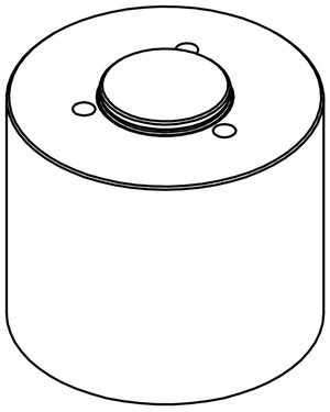
Each chuck has a corresponding diameter for alignment on its backside as shown here:
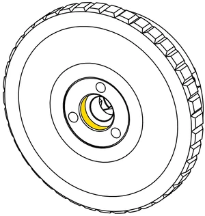
The tap of the fixture should preferably has the following size:
| Type | Ø of tap |
|---|---|
| DBF34 | Ø14H6 |
| DBF55 | Ø14H6 |
| DBF63 | Ø12H6 |
| DBF100 | Ø24H6 |
| DBF140x58 | Ø58H6 or Ø85H6* |
| DBF160 | Ø28H6 |
| * The DBF140x58 also provides an outer diameter for alignment on the backside | |
Please note that best results can be achieved when the tap diameter is fitted individually to each chuck. The adaptation of the chuck is a crucial part in achieving a minimal radial run-out.